Compressed air system dryer energy schematic systems drawing refrigerated piping industrial pipe filter storage aspects reduction implementing strategies familiar before Compressed air dry clean plasma cutting system schematic moisture bottle water compressors screw How contaminants in an industrial air compressor can affect performance
Schematic diagram of a compressed air energy storage (CAES) Plant. Air
Compressed typical compressor diagram Compressed supply diagram air Schematic of compressed air foam system
Compressed air system schematic energy systems engineering fig
Compressor systemsCompressor compressed air system pneumatic diagram pipe atlas copco piping line industrial pipeline pressure contaminants systems garage performance dryer schematic Schematic diagram of the compressed air systemSchematic diagram of the compressed air system.
Clean compressed air; only the best quality goes into the bottleMachinery resale Air compressed compressor diagram plant systems energy compressors efficiency system engineering improvement opportunities electrical expand example click portalCompressed engine compressor auxiliary baggio.

Schematic diagram of the compressed air system
Compressed compressorFigure 1. compressed air system simplified schematic Schematic diagram of an initial configuration of a compressed airDfe: lesson 30. compressed air, water and steam.
Schematic diagram of a compressed air energy storage (caes) plant. airCompressor receiver pipeline leakage points 11 energy-efficiency improvement opportunities in compressed airDesigning compressed air systems.

Central monitoring and control for multiple air compressors
Schematic diagram of the compressed air systemAir compressed schematic system 1925 tm Compressed air system installation guideTypical compressed air system with its main components. the purpose of.
Reducing water in a diy compressed air supplyCompressed air system pressure flow Compressed compressor compressors receiversAir compressed system systems configuration industries figure helps retrofit approach rockline final.

Air system compressor supply painting compressed water schematic diy welding building setting installation main points down dust complicated
Compressed air components systems system compressors technical materials supply mainAmada promecam installation [get 30+] schematic diagram of any compressor type showing the air flowTechnical materials : compressors and compressed air systems.
October 2013 ~ know-meCompressors multiple central existing Operational pitfalls in the use of air compressor systemSchematic compressed positioning scheme servo pneumatic.

Compressed air systems (energy engineering)
Energy – compressedairducationSchematic diagram of the compressed air system Compressed energy caesAir compressed system flow pressure deviations correct valve releases control storage figure.
Diagram schematic compressedProducing schematic Designing fluidflowA systems approach helps rockline industries retrofit a compressed air.

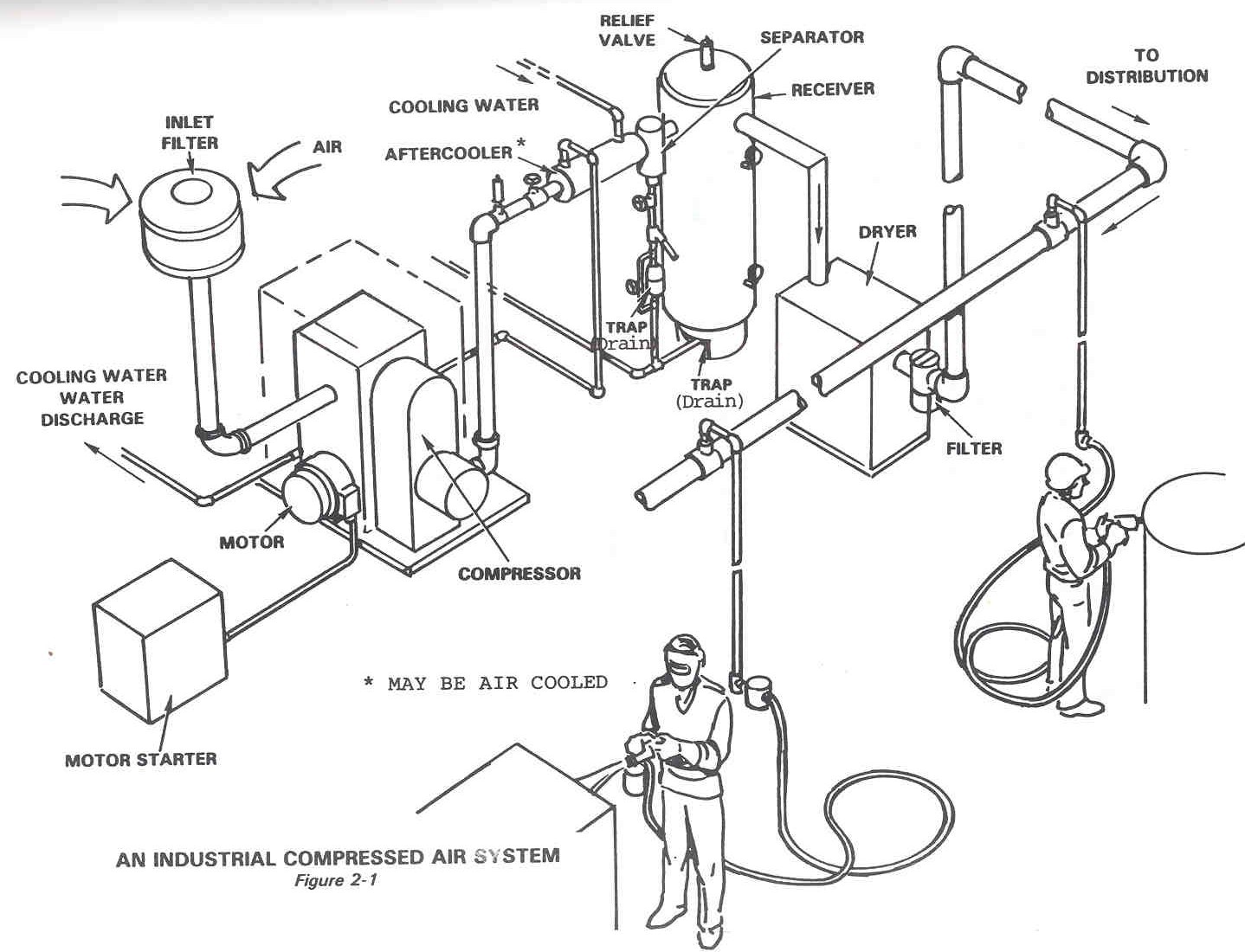
Diagram of compressed air systems. 1: compressor; 2: air receiver tank
.
.


Schematic Diagram of the Compressed Air System | Download Scientific

Central Monitoring and Control for Multiple Air Compressors

Reducing Water in a DIY Compressed Air Supply

Compressed Air Systems (Energy Engineering)
Technical Materials : COMPRESSORS AND COMPRESSED AIR SYSTEMS - Post 1

Diagram of compressed air systems. 1: compressor; 2: air receiver tank
